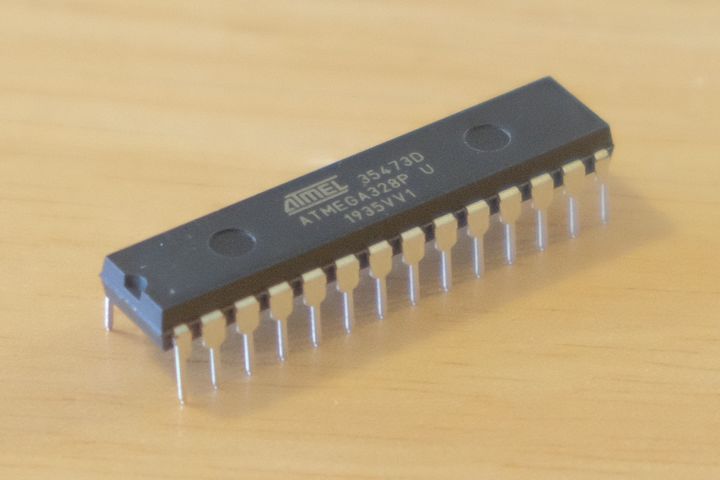
The Arduino Uno is a readily available development board for the Amtel ATmega328 microcontroller, allowing the user to easily experiment and iterate with their design. For use in an actual product, or to make a one off gadget even smaller, it is advantageous to use the microcontroller chip independent of the Arduino board. These notes look at operating the ATmega328 by itself on a breadboard, and how to program the chip in situ using an Arduino.
Correctly programmed, the atmega is able to run without any external components, using one of two internal clock oscillators.
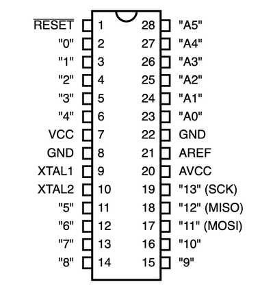
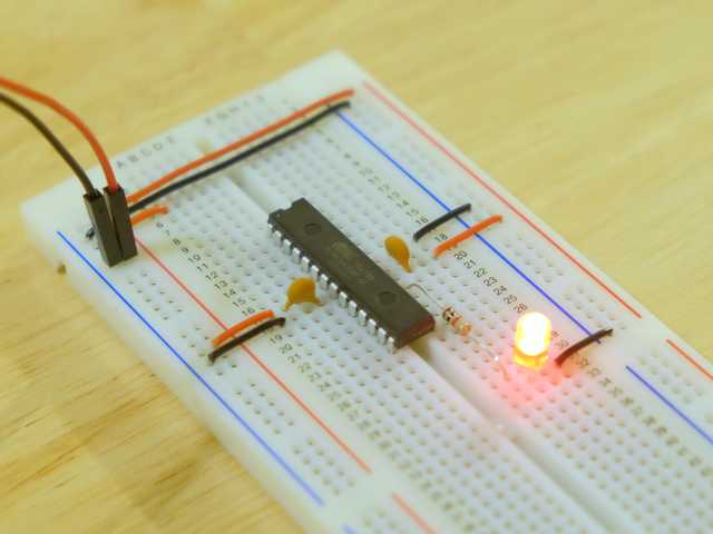
Power is supplied to pins 8, 22 (ground) and 7, 20 (+V)
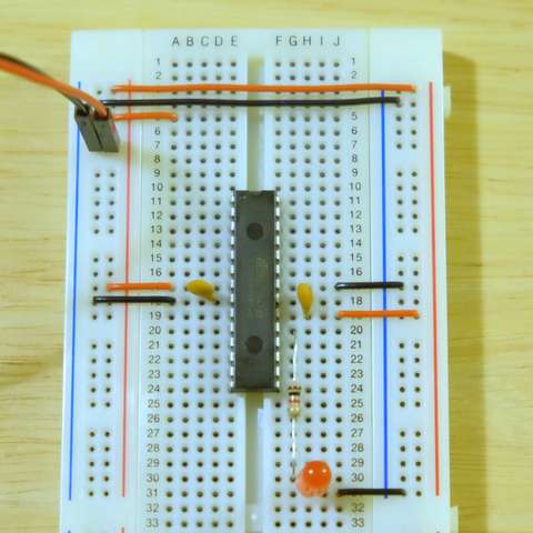
An example is shown above on a breadboard - the only extra components are two .1uF capacitors bypassing the supplies at the chip, and an LED (with 1k resistor) hung off pin 19 (port pin PB5). IC pin 19 is digital pin 13 in Arduino land, where the onboard LED is connected, making this setup compatible with Arduino sketches such as Blink.
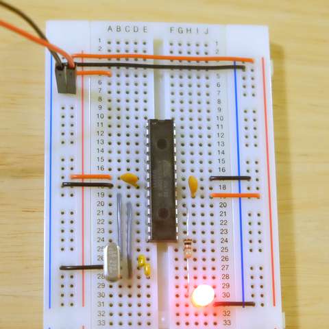
When greater timing accuracy or a higher speed is required, a crystal can be used for generating the clock - this is the setup used on the Arduino board.
An unprogrammed ATmega328 is supposed to come setup to use the
internal oscillator; the examples I had to hand were seemingly preprogrammed to
use the crystal so it was required for initial programming.
Programming an ATmega328 in serial mode from an ArduinoISP requires the following connections:
| Arduino pin 10 → ATmega328 pin 1 (RESET) |
| Arduino pin 11 → ATmega328 pin 17 (MOSI) |
| Arduino pin 12 → ATmega328 pin 18 (MISO) |
| Arduino pin 13 → ATmega328 pin 19 (SCK) (Also connected to LED) |
It is safe to connect the Arduino board pins directly to target
microcontroller as the ArduinoISP sketch handles the communication pins
carefully before and after programming to prevent two outputs being
connected together. [1]
These examples will upload the Blink sketch onto the target.
For comparison, this is the usual procedure for programming an Arduino Uno board directly. (If trying this, be sure the Arduino is not connected to the breadboard at this time.)
Note that depending on operating system and setup, the name under Tools > Port may vary. When uploading directly to an Arduino, the setting of Tools > Programmer does not matter.
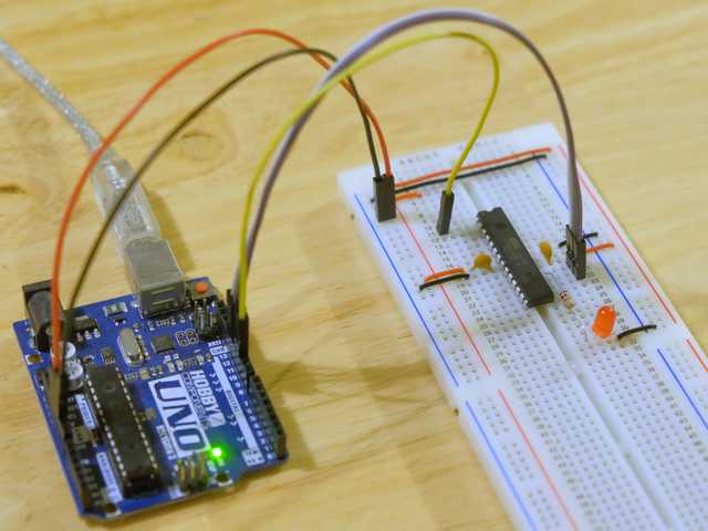
An Arduino board can be turned into an ISP (In System Programmer) for uploading code to a bare microcontroller using the sketch ArduinoISP.
Pins 10, 11, 12, 13 (and ground - and power if required) can then be connected to the breadboard/in-system microcontroller as given in the hardware section above.
With an Arduino set up as an ArduinoISP, connect it to the ATmega328 that is on the breadboard or in-system. See hardware section above.
To successfully program the bare microcontroller, we have to set Tools > Board and Tools > Programmer correctly.
The Tools > Board setting is used to determine the processor frequency (for making time based functions such as delay() work correctly), and for setting fuse bits when burning the bootloader.
Tools > Programmer must be set to "Arduino as ISP" to correctly use the Arduino programmed as an ISP.
An ATmega328 setup with a 16MHz crystal can be programmed successfully from the stock Arduino IDE with Tools > Board set to "Arduino Uno".
The crucial step is using 'Upload Using Programmer' on the Sketch menu. This will upload the sketch via the ArduinoISP to the second ATmega. Holding down shift while clicking the upload toolbar button also works. (However see below, a suitably configured board specification will obviate this and allow using Upload as normal)
Determining fuse bits requires the correct settings in the boards.txt within a platform specification, which is what is chosen with the Tools > Board setting.
The following examples assume the In System MCU platform is installed.
To set the fuse bits, choose a "Board" with appropriate settings and use "Burn Bootloader" - fuse bits can only be written from the IDE when also burning the bootloader.
Note that when reprogramming a used microcontroller, if it has previously been set to require a clock crystal, this will need to be provided whilst setting the fuse bits, otherwise it will have no clock and be unable to communicate with the programmer.
Once the fuse bits have been set as desired using Burn Bootloader, compiling and uploading a sketch proceeds in the usual manner.
I have created a custom platform called In System MCU which provides various useful fuse settings. A zero-size 'bootloader' is provided with each of these board settings, and fuses are set to allow the entire flash memory to be used for the sketch. They are also configured so as to conveniently force the IDE to use "Upload Using Programmer" when the user selects "Upload". [2]
The custom platform is available for manual installation from GitHub, or can now be installed via the Boards Manager:
See notes below on creating a platform specification.
On reset, data direction registers are initialised to 0, making all port pins inputs.
ArduinoISP - pulls down target's RESET line before setting Arduino's comminication pins as outputs. (Reading ArduinoISP source code: start_pmode() calls reset_target() then calls SPI.beginTransaction() which will set up communication pins as outputs. start_pmode() is called from avrisp() which is called from the loop. avrisp() chooses what to do by calling getch() which calls Serial.read() to recieve communication from the IDE)
After programming, ArduinoISP sets the communication pins to inputs before bringing the target out of reset. (end_pmode() called from avrisp())
Within boards.txt, leaving out boardname.upload.protocol forces the IDE to use Upload Using Programmer when the user chooses Upload.
Fuses
| Function | ATmega328P Default | My Fuses | Arduino Uno |
|---|---|---|---|
| High Fuses | |||
| External Reset | 1 = Enabled | ||
| Debug Wire | 1 = Disabled | ||
| Serial Programming | 0 = Enabled | ||
| Watchdog Timer | 1 = Not Always On | ||
| EEPROM | 1 = Not Preserved During Flash | ||
| Bootsize | 00 2048 words | 11 = 256 words | 11 = 256 words |
| Boot Vector | 1 0x0000 | 1 = 0x0000 | 0 = 0x3f00 |
| Low Fuses | |||
| Divide Clock By 8 | 0 = Yes | ? | 1 = No |
| Clock Output on PORTB0 | 1 = No | ||
| Startup Time | 10 = 14CK + 65ms | ?? = 14CK + 65ms | 11 = 14CK + 65ms |
| Clock Select | 0010 = 8Mhz Internal | ? | 1111 = Low Power Crystal 8-16MHz |
| Extended Fuses | |||
| Brown Out Detection | 111 = Disabled | 101 = 2.7V | 101 = 2.7V |
CKDIV8 fuse merely detemines the after reset value of CLKPR Clock Prescale Register to be either 0000 (divide by 1) or 0011 (divide by 8). This can be changed from software once the processor is running.
CLKPR = 0x80;    /* prepare to change prescaler value - required by hardware */
CLKPR = 0x03;    /* divide clock by 8 (2^3) */
Useful Fuse Combinations
High Fuses = 0xDF 1101 1111
Extended Fuses = 0xFD
Low fuses:
| Divide by 8 | Startup Time (14CK + 65mS) | Clock Select | Low Fuse Value | |
|---|---|---|---|---|
| 16MHz (8-16MHz+ Crystal) | 1 | 11 | 1111 | 0xFF |
| 2MHz (8-16MHz+ Crystal) | 0 | 11 | 1111 | 0x7F |
| 8MHz Internal | 1 | 10 | 0010 | 0xE2 |
| 1MHz Internal | 0 | 10 | 0010 | 0x62 |
| 0.128MHz Internal | 1 | 10 | 0011 | 0xE3 |
| External Clock | 1 | 10 | 0000 | 0xE0 |
For low clock speeds (eg. internal 128 kHz) have to slow down SPI for programming in ArduinoISP - change line 53:
#define SPI_CLOCK (128000/6)
Loop doesn't run at low clock speed?
At low clock speeds, there is not enough time for interrupts to complete, specifically the millisecond interrupt, causing the microcontroller to hang.
Arduino IDE also hides stuff in ~/Library/Arduino15
A custom Board can be specified by creating a folder within ~/Documents/Arduino/hardware. Within this folder must be a subfolder 'avr' containing the specification files.
Required files are boards.txt, platform.txt, and a bootloader .hex file.
Platform.txt only has to define a name and version. The name is shown as a subheading in the Tools > Boards menu.
avr/platform.txt
name=In System MCU
version=1.0.0
The bootloader must be in a further subfolder 'bootloaders'. It is Intel Hex format; a null file can be created with only an end of file record.
avr/bootloaders/nullboot.hex
:00000001FF
boards.txt defines various things, including the expected processor speed and fuse bits to use when burning the bootloader.
ismcu_atmega328p16.name=ATmega328P 16 MHz (16 MHz Crystal)

ismcu_atmega328p16.upload.tool=arduino:avrdude
ismcu_atmega328p16.upload.maximum_size=32768
ismcu_atmega328p16.upload.maximum_data_size=2048
ismcu_atmega328p16.upload.speed=57600

ismcu_atmega328p16.bootloader.tool=arduino:avrdude

ismcu_atmega328p16.bootloader.low_fuses=0xFF
ismcu_atmega328p16.bootloader.high_fuses=0xDF
ismcu_atmega328p16.bootloader.extended_fuses=0xFD

ismcu_atmega328p16.bootloader.unlock_bits=0x3F
ismcu_atmega328p16.bootloader.lock_bits=0x3F
ismcu_atmega328p16.bootloader.file=nullboot.hex

ismcu_atmega328p16.build.f_cpu=16000000L
ismcu_atmega328p16.build.mcu=atmega328p
ismcu_atmega328p16.build.board=AVR_UNO
ismcu_atmega328p16.build.core=arduino:arduino
ismcu_atmega328p16.build.variant=arduino:standard
Installation archive: remove boards.txt, platform.txt, bootloaders/ from avr/ subfolder and place in root of what will become .zip archive. Host installation archive online eg. via github.
package_????_index.json file to be hosted elsewhere than installation archive.
{
  "packages": [
    {
      "name": "In System MCU",
      "maintainer": "Jason Bamford",
      "websiteURL": "http://www.bamfordresearch.com/",
      "email": "",
      "platforms": [
        {
          "name": "In System MCU",
          "architecture": "avr",
          "version": "1.0.0",
          "category": "Contributed",
          "help": {
            "online": "http://www.bamfordresearch.com/arduino-platform"
          },
          "url": "https://github.com/jb-23/in-system-mcu/archive/refs/tags/bm1.zip",
          "archiveFileName": "In-System-MCU-1.0.0.zip",
          "checksum": "SHA-256:174415C70E69364FEC88809892618D5B703595DF9BAB97B661345A77A53D7E7B",
          "size": "3284",
          "boards": [
            {"name": "ATmega328P (8-16+ MHz Crystal)"},
            {"name": "ATmega328P (8 MHz Internal)"}
          ],
          "toolsDependencies": []
        }
      ],
      "tools": []
    }
  ]
}
To generate checksum and size: download target zip, run `shasum -a 256 file.zip` and `stat file.zip`.