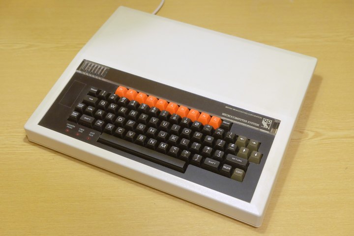
The BBC Micro was a Microcomputer made by Acorn Computers; introduced at the end of 1981 as part of the BBC Computer Literacy Project, it was succesful both as home computer and in the educational market, with most schools in the UK using the machine for computing education. During the 1980s and 1990s, using a BBC Micro in primary school was the first experience of a computer for many people - including the author.
This example, despite being in immaculate physical condition, really wasn't happy when turned on; it seemed to put out a very bad video signal. Sometimes it appeared it was trying to work, but the picture would judder wildly.
Testing with an oscilloscope revealed the video signal looked ok, but on closer examination the vertical sync rate was 80Hz, obviously not to the liking of the 50Hz monitor!
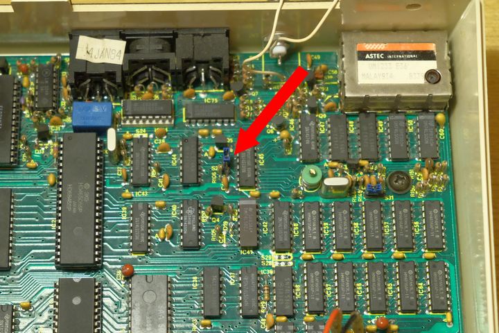
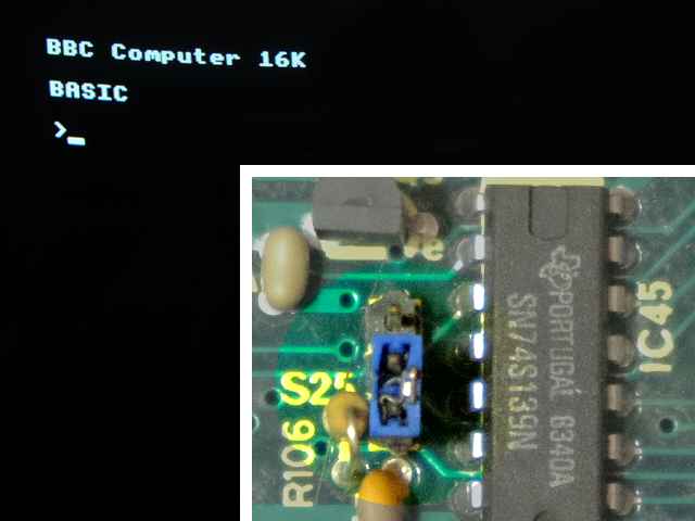
A little research and head scratching later I figured out this is symptomatic of a RAM fault, causing the CPU to read garbage values that then get written into the 6845 video controller during boot, resulting in the weird output frequency. Further I came across a trick of moving a jumper on the motherboard (S25) to disable half the RAM, and this indeed worked, the machine operating happily and reporting itself with 16k of memory. [1]
In this case this isolated the issue to the jumpered-out half of the RAM. Each 16k of RAM is made from 8 ICs, and likely not all of these were faulty - a way was needed to test them, ideally in situ as they are soldered to the board.
If it was possible to swap the two RAM halfs, this would put the faulty chip into the video memory, where it would not crash the machine during boot. [2]
Swapping the two RAM halfs electronically is possible - jumper S25 actually carries a signal used to select which half of RAM is operating, and inverting this signal as it passes through the jumper will swap the memory banks over. [3]
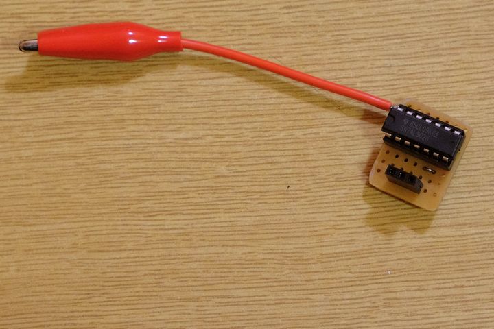
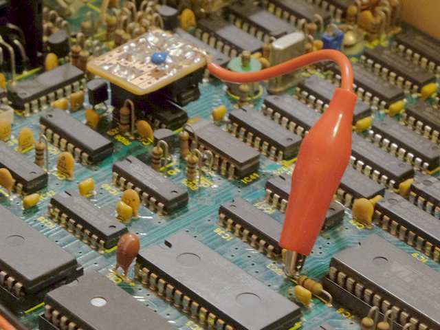
To achieve this I created a small circuit board with a header that fits in place of the jumper. [4] The board carries a quad-nor gate used to invert the signal [5] The jumper header does not carry a +5V power line so a flying crocodile lead was used to reach the +5V rail on one leg of a nearby resistor. The circuit board had to be carefully designed to fit amongst the components surrounding the jumper header; note in the pictures I hung a supply bypass capacitor off the solder side of the board.
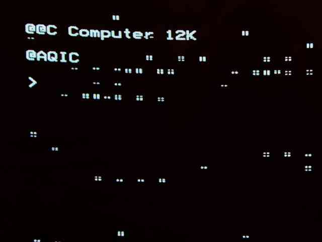
With the inverter circuit in place, the machine booted up and repored a full 32k of memory - or tried to, the message on screen was a little garbled due to using the faulty IC for video memory - made worse by booting up in Mode 7.
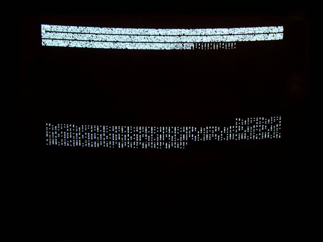
Changing to a bitmapped graphics mode and typing demonstrated the effect of the bad memory. Typing in one location on screen, multiple parts of the screen were written to - clearly writes to the bad IC were incorrectly happening to multiple locations at once.
With the fault safely confined to video memory and the machine now booting, I worked on writing a BASIC program to run on the machine that could test the RAM by writing and reading it strategically to figure out which IC is faulty.
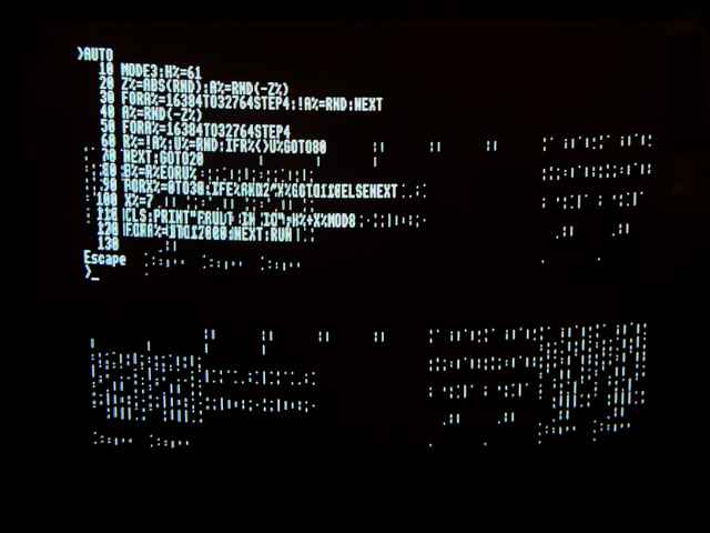
A listing of the program is given here in case it is of use. See the notes section for an explanation of how it works. [6]
 10 MODE 3 : H%=61 : REM - MEMORY SWAPPED H%=61 - NOT SWAPPED H%=53
 20 Z% = ABS(RND) : A% = RND(-Z%)
 30 FOR A% = 16384 TO 32764 STEP 4 : !A% = RND : NEXT
 40 A% = RND(-Z%)
 50 FOR A% = 16384 TO 32764 STEP 4
 60 R% = !A% : U% = RND : IF R% <> U% GOTO 80
 70 NEXT : GOTO 20
 80 E% = R% EOR U%
 90 FOR X% = 0 TO 30 : IF E% AND 2 ^ X% GOTO 110 ELSE NEXT
100 X% = 7
110 CLS : PRINT "FAULT IN IC"; H% + X% MOD 8
120 FOR A% = 1 TO 12000 : NEXT : RUN
Note the REMark on line 10 - it is not necessary to type in the REM part of the line, but it serves to draw attention to the H% = 61 assignment immediately before it, which must be changed depending on whether the memory is swapped around with the inverter circuit, as this affects which RAM IC will be identified as faulty. [7]
As with most BASIC dialects of that era, it is possible for brevity to type the program into the machine without any spaces; indeed doing so will make it run faster. The code is presented above with spaces to make it easier to read.
The program is short enough to key into the machine fairly quickly (I did it several times without getting bored). When reading it off the screen to verify what's been typed, care must be taken if trying to see through any messed up pixels due to the bad memory.
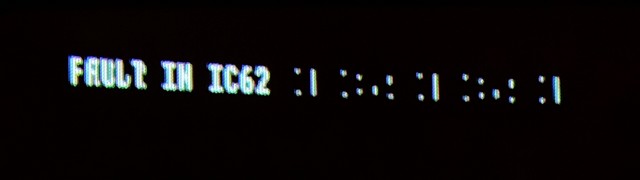
The program runs and reports IC62 is faulty. [8]
Breif attempts at desoldering the RAM IC made it clear this was not happening, making it necessary to resort to violence. Out came the dremel and I carefully cut all the legs of the IC close to it's body. With the body removed, each individual leg was be desoldered while pulling on it from the component side of the board. This minimised damage to the PCB by reducing the amount of heating required.
With the faulty IC removed and the board cleaned up, fitting a suitable
IC socket and populating it with a new chip was the easiest part of the
whole project.
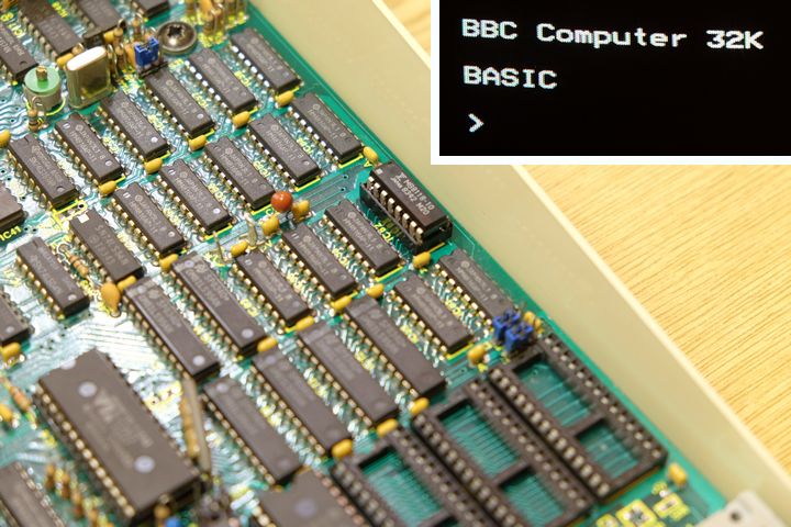
After replacing the single IC and returning the jumper to normal, the machine once again ran happily with it's full 32k of memory.
The BBC Model B uses 16 individual DRAM (dynamic RAM) ICs to make up it's 32kB of RAM. Each IC stores a single bit's worth of memory for each of 16k addresses - requiring 8 chips for each 16kB of RAM.
The lower cost Model A left out half of these chips, and used the jumper used here to prevent the machine trying to access the non-fitted ICs.
Various DRAM ICs may be found in the BBC Model B; my example was originally fitted with HM4816AP-11 parts, and the replacement I sucessfully used is a MB8118-10.
Moving the jumper causes the computer to use the 'upper' half of RAM, ignoring the 'lower' half, which in this case was where the fault lay. If the fault appeared in the 'upper' half of RAM, which is used primarily for video data, it would not cause the computer to crash during boot, although it may cause inteference on screen.
The 16k jumper position merely ties the signal to the RAM low. The 32k position allows through a signal from the processor allowing it to chose between the first and second 16k of memory. Inserting a circuit to reverse this signal swaps the two halfs of RAM and moves the fault from the critical lower half to the upper half.
The connections on the S25 jumper header are:
| North | Output from IC28 (connect to input of the inverter) |
| Center | Input to IC45 (selects RAM bank - connect to output of the inverter) |
| South | Ground |
South is towards the keyboard; north is away from the keyboard.
I used a quad-NOR gate IC as this had the most favourable orientation of input and output pins amongst the ICs I had to hand. Only one of the gates is used, configured as a simple inverter, the remaining gates have their inputs tied to the nearest power rail and their outputs open.

I initially tried to make a simple single transistor inverter, but for whatever reason the circuit was not fast enough. The computer did boot but the screen only displayed colourfully garbled mayhem.
How the program works:
Resident integer variables are used throughout to maximise performance and minimise the amount of typing (these are denoted by a single letter followed by a % symbol).
Line 10 sets video mode 3, which uses 16kB of memory and therefore uses all of the upper half of RAM for the screen. This prevents BASIC from trying to use any of the faulty memory and allows us to write all over it during testing.
Line 20 randomly chooses a seed value (kept in Z%) and then seeds the random number generator with it. The RAM is then filled with radomly generated data (FOR loop on line 30). Since the Beeb uses 32 bit integers, we can actually work through memory four bytes at a time (STEP 4) which makes things faster.
The random number generator is re-seeded (line 40) with the same value chosen on line 20; it will thus reproduce the series of random numbers it has just generated.
Lines 50-70 go back through memory, comparing the values read to the re-generated random sequence that was stored.
When an error is detected, we jump to line 80, where an exclusive-or function is used to detect which bits of the four bytes have been changed. We then loop over each of the bits (line 90), and jump to PRINT the result when we find a changed bit. Thankfully the component numbers used for the RAM ICs are laid out sequentially, making it easy to 'calculate' which IC has the fault.
The final line of the program creates a delay of several seconds so the result can be read, before returning the beginning to repeat the test (if multiple ICs have failed, a different result might occur each time).
While the program is running, the screen is seen filling up with random black and white pixels, followed by a pause while they are read back and compared. If there are no faults, after the pause, no message is displayed and the screen will be written over again with a new random set of data.
The first line of the program sets the variable H%, and must be changed depending on whether or not RAM has been reversed as described in this post. When RAM is not reveresed (the jumper in it's standard position), ICs 53 through 60 are tested - when RAM is reversed (jumper replaced with an inverter), ICs 61 through 68 are the ones being tested.
The location of the fault can be verified by very careful examination of which pixels of each character are impacted by glitching. In this case, a fault in IC62 makes sense as this is the second least signficant bit, and in Mode 3, errors occur in what looks like the second pixel from the right in each character.
I have since come across a similar project where the author experienced an analogous story arc.